


- Early air navigation relied on radio direction finding techniques developed even before World War I, using ground-based loop antennas to determine an aircraft’s bearing from its radio transmissions.
- During and after World War II, direction finding evolved through systems such as HF/DF and VHF Direction Finders, with innovations like the goniometer replacing mechanical antenna rotation and greatly improving speed and practicality.
- The later adoption of Commutated Aerial Direction Finding (CADF) marked a technological milestone, delivering higher accuracy, multi-channel capability, and integration with radar, reinforcing the role of direction finding in modern air traffic control.

As aviation operations expanded beyond purely visual methods of navigation, the need emerged to derive and provide directional information from the ground to support Air Traffic Control (ATC) and enhance the safety of air traffic.
These systems used aircraft transmissions to determine the aircraft’s direction of travel. Information is provided in terms of QDM or ‘magnetic bearing to’ (inbound) and QDR or ‘magnetic bearing from’ (outbound).
Multiple Direction Finder stations were used to pinpoint an aircraft’s position (fix) by intersecting their individual bearings. Radio Direction finding was a widely used technique even before World War I, used for both for nautical and aeronautical navigation. The basic concept used a loop antenna, in its most basic form simply a circular loop of wire with a circumference decided by the frequency range of the signals to be detected. When the loop is aligned at right angles to the signal, the signal in the two halves cancels out, producing a sudden drop in output known as a “null”.
High-Frequency Direction Finding
Also known by its abbreviation HF/DF, or Huff-Duff, is a type of Radio Direction Finder (RDF) that was introduced in World War II. HF/DF was primarily used to intercept enemy radio transmissions, but it was later used during the post-war period to facilitate air traffic control.
This basic technique remains in use even now as one of the fundamental disciplines of signal intelligence, although typically incorporated into a larger suite of radio systems and radars instead of being a stand-alone system.
In the earlier systems, operators used to mechanically rotate a loop antenna or solenoid and listened for peaks and nulls in the signal to determine the bearing (direction) of the transmitter. This process took considerable time, of the order of a minute or even more. Radio operators on board the aircraft would try to avoid being located by keeping their messages short.
VHF Direction Finder (VDF)
VDF is a ground-based system that uses a directional antenna to determine the bearing (direction) of VHF radio transmissions from aircraft and provide that information to air traffic control. It works by analysing the direction of arrival (DoA) of radio waves, often using antenna arrays and digital processing, allowing controllers to guide pilots, especially in low visibility, by giving them a precise bearing to follow. VHF Direction Finding relies on the basic characteristic of electromagnetic waves, which is that the electric and magnetic vectors are perpendicular to the direction of propagation. Direction Finding essentially employs one of the following two methods:
- Measures the direction of electric and/or magnetic field vectors – polarisation direction finders (rotating loop, etc)
- Measures the orientation of surfaces of equal phase (or lines of equal phase if the elevation is not of interest) – phase direction finder (Directional antenna, max/min direction finder)
Goniometer
It was realised that physically rotating an antenna to determine the direction of arrival of an electromagnetic signal (such as an aircraft transmission) was not only cumbersome but also slow. So goniometer was used to electronically simulate the rotation of an antenna.
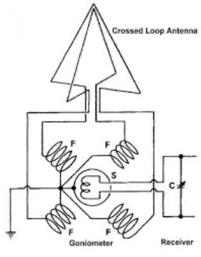
In 1907, Ettore Bellini and Alessandro Tosi suggested an improvement to simplify the operation of the Direction Finding system.
A single loop antenna was replaced by two antennas arranged at right angles. The output of each was sent to its own looped wire called “field coil” (Fig 2). Two coils, one for each antenna, were arranged close together at right angles.
The signals from the two antennae generated a magnetic field in space between the coils, and this field was picked up by a rotating solenoid called the “search coil”.
Maximum signal was generated when the search coil was aligned with the magnetic field from the field coils, which was at the angle of the signal in relation to the antenna. This system was patented in the United States in 1909. This eliminated any need to mechanically rotate the bulky antenna.
VHF Direction Finder Type Marconi AD 200/AD 210C
Marconi, a British telecommunication and engineering company, developed the Marconi AD200 in the early 1950s to provide bearing information to the Air Traffic Control.
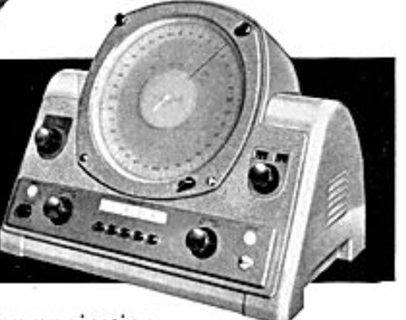
Aerial assembly consisted of Type 1561 elevated H-type aerials mounted on a tubular mast.
Type 1562 local receiver equipment had two receivers to analyse input from the goniometer, and bearing information was displayed on a single 8-inch-diameter display.
Later, AD210C was developed to incorporate five VHF channels. A slave display unit could be incorporated (up to 150m away).
This facility was used in DGCA (now AAI) Air Traffic Control units. This system has been subsequently replaced by direction finding systems, which were based on Commutated Aerial Direction Finding (CADF).
Commutated Aerial Direction Finder (CADF)
CADF was first developed, and trials were conducted in the United Kingdom between 1945 and 1947. Subsequently, systems were developed to operate on VHF/UHF and HF bands in 1954.
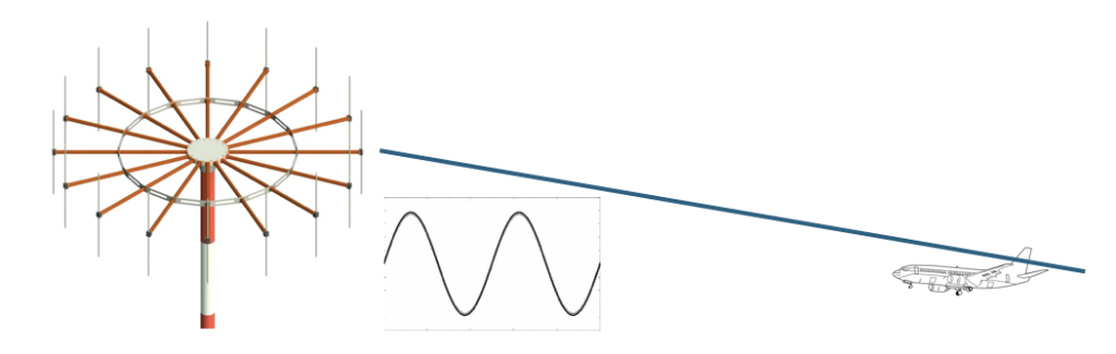
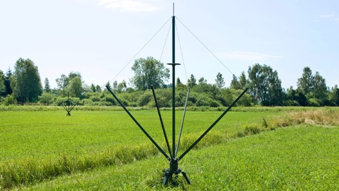
The CADF antenna system consists of multiple dipoles arranged in a circle around a central pole. These dipoles are switched using an electronic commutator to connect each antenna sequentially in the ring to the receiver. Rapid switching effectively simulates the movement of the receiving point around the circle, creating a synthesised Doppler frequency shift similar to a physical Doppler system but without any actual movement.
The Receiver analyses the phase and frequency shifts (due to the Doppler effect) of the incoming signal to determine the direction of radio transmission. Doppler shift will be maximum positive/negative when the aircraft transmission is being received from the antenna lying on a line which is perpendicular to the direction of the received signal, and shift will be minimum when the antenna lying along the direction of receipt of signal is receiving the transmission. The position of the antenna which corresponds to the minimum shift (zero) with respect to the North antenna will give the bearing.
Technically, CADF gives much better resolution and accuracy, and also, the same system can be used for multiple channels simultaneously. Sometimes, information provided by CADF is also fed to the radar display.
Conclusion
A need was felt to provide bearing information to ground-based Air Traffic Controllers to help them incorporate aircraft separation. This not only enhanced airspace capacity but also improved operational safety.
Also Read: History of Air Navigation – Part II: Transition to Radio Navigation Systems