


- Navigation systems have evolved significantly since the Viking era, with Tactical Air Navigation (TACAN) now widely used for air and sea travel.
- After World War II, the need for reliable navigation systems became critical for safety and efficiency, leading to the development of advanced technologies like TACAN.

Globally, Non-Directional Beacons (NDB), Very High-Frequency Omnirange (VOR/DVOR)) and Distance Measuring Equipment (DME) systems have been adopted by the international civil aviation community for providing ranging and azimuth information to the aircraft. Some countries (like the USA) have accepted the Tactical Air Navigation System (TACAN. as azimuth and distance navigation aids, though this system has not been accepted as a standard ICAO navigation system.
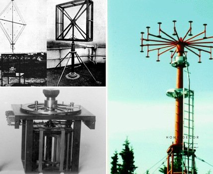
Tactical Air Navigation (TACAN) system evolved from Radio Transponder navigation system that was developed from the concept used for British Oboe system used during World War II. Post war, many companies in USA got involved in the development of TACAN for military aircraft. Hoffman Laboratories (Hoffman Electronics Corp. – Military Products Division) led the project starting in late 1950s.
A Tactical Air Navigation (TACAN) system is essentially a defence system which can be installed on the ground, on buildings or on ships. It provides to the using aircraft, its positional information (azimuth and distance) with respect to the ground-based beacon. Positional information is provided in terms of its Rho (r)Theta (q) in the Polar Coordinate system, where Rho (r) is the distance in nautical miles (or Km) from the beacon and Theta (q) is the bearing angle w.r.t Magnetic North. Figuratively, the positional information, with reference to the ground-based beacon, can be represented as in Fig 1.

Information provided by TACAN is the same as the information provided by VOR(DVOR)/DME in Civil Aviation, however TACAN has many advantages over conventional DVOR/DME systems. Some of the advantages are described below:
TACAN Advantages:
Resolution: VOR/DVOR resolve bearing information at 30Hz, in TACAN the bearing information is derived in two stages. Coarse bearing information is derived from 15Hz signal which is then refined by signal at 135Hz. Theoretically resolution of bearing information in TACAN is hence much better as compared to DVOR/VOR.
Size: DVOR/DME are two different autonomous (except for Ident) systems having their own independent equipment and antenna system as compared to the single equipment and antenna system for TACAN. This results in increased space requirements for DVOR/DME and associated environmental control and standby power supply requirements. In addition, DVOR has an elaborate antenna system which makes the space requirements and civil construction much more elaborate.
Site Restrictions: DVOR performance is significantly affected by the terrain conditions and obstructions around the antenna system. Since TACAN uses vertical polarisation, the adverse effects of ground conditions (in the vicinity of its antenna) on the performance of TACAN are considerably lesser. TACAN System also rejects multipath signals generated by nearby obstructions by using signal processing techniques (like disregarding multipath signals). Bearing performance has been observed to be considerably more stable as compared to VOR/DVOR. Also, significantly lesser course bends, scalloping and course roughness is observed[6] as compared to DVOR.
Single Frequency: DVOR uses spot frequency in VHF band and DME uses frequency in the UHF band, thus two frequencies (one for DVOR and the paired frequency for DME) are required to be used. TACAN, however, works on a single frequency in the UHF Frequency Band, resulting in the spectrum conservation. It may be mentioned that whereas DVOR uses an exclusive frequency (band 111.975MHz to 117.975MHz), TACAN uses assigned frequency (band 960MHz to 1215MHz) and shares the band with DME and other systems. A total of 252 channels are divided into two groups of 126 channels each. ‘X’ group with channels numbered from 1X to 126X and ‘Y’ group with channels 1Y to 126Y[5].
Installation Convenience: Because of its small size and no requirement of installing an elaborate antenna system, it is relatively much more convenient to install TACAN as compared to DVOR. In fact, TACAN can be installed on top of a building also. In addition, because of its relative immunity from the harmful effects of multipath (because of obstructions close to the antenna systems) site evaluation and siting restrictions are much more liberal. In fact, TACAN can be installed on board a ship in spite of the existence of multiple obstructions very close to the antenna system.
Air-to-Air frequency pairing: 63 pairs of Air-to-Air (A/A) channels in X-mode and 63 pairs in Y-mode shall be available for A/A link between two interrogators[5] on board the aircraft.
In the event of bearing signal not being available in TACAN, system shifts to DME Only Mode, in which it continues to provide distance information to both civil and defence air traffic[5].
TACAN, however is not a standard International Civil Aviation Organisation (ICAO) navigation aid and hence is not used by international civil aviation. TACAN, though can be used by the civil aviation traffic for getting distance information from DME portion of the system without any restrictions. TACAN can also be co-located with DVOR in the VORTAC configuration, so that systems at the same location can be used by civil aviation and defence air traffic and procedures can be designed with same waypoints.
Principles of Operation
As explained above, TACAN provides
- Distance information
- Bearing information with reference to Magnetic North
The principles used to generate these two pieces of information are totally different and, hence, are described separately.
Distance Information (DME):
Since concept used for providing distance information in TACAN is exactly the same as in the conventional DME, the subject is being taken up very briefly here.
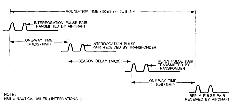
The distance measuring concept in TACAN equipment is an outgrowth of the radar-ranging technique. Ranging concept used in Radar (Secondary Surveillance Radar or SSR) determines the distance by measuring time taken by modulated Radar pulses transmitted by ground beacon, received in the transponder on board the aircraft and the modulated reply pulses generated by the transponder and received in Radar (SSR) interrogator. In DME/TACAN, to-and-from distance is measured on board the aircraft by using the concept, but interrogations, in this case, are generated by the airborne systems, and the ground beacon system responds to them after incorporating fixed station delay. The aircraft system measures the time taken (minus the station delay) and converts half this time to the corresponding distance (1Nautical Mile is approximately = 6mS).
Pulse pair (with specified pulse shape, spacing and other parameters), modulated over an assigned RF interrogation carrier (one of the 126 channels), is transmitted by the aircraft interrogator, which is received in the ground transponder and analyzed to validate the interrogations. After the interrogation is validated, the reply pulse pair (with specified pulse parameters) is modulated over the assigned reply RF frequency and transmitted as a reply. Specified station delay is added to the reply pulses before modulating them over the assigned reply frequency. The airborne interrogator measures the time taken by the interrogation pulse pair to travel over the slant distance to the beacon and reply from the ground beacon (minus the station delay). Half this time is then converted to the corresponding slant distance (6mS of delay corresponds to 1 NM distance). The concept can be represented as explained in Figure 2.
It may be noted that both TACAN and DME provide slant distance and not the distance over ground. This slant distance reading is sufficiently close to the distance on ground, if the aircraft is quite far of. If the aircraft is close to the beacon, the ground distance can be calculated using slant distance measured and altitude readings.
For the transponder to operate satisfactorily, the average power supplied to the antenna must be generally uniform over time, or the transponder should operate on a constant-duty-cycle. To achieve this requirement, the receiver uses automatic gain control (AGC) and squitter (random noise pulses) to maintain constant transponder output power. If the interrogations received by the ground-based transponder are too less, the gain of its receiver is increased to add noise/far off interrogations or additional random noise pulses (squitter) are generated.
Approximately 120 airborne interrogators can simultaneously interrogate a single ground-based beacon. Initially, when the aircraft switches on the airborne system or when aircraft enters the coverage airspace, interrogation starts in Search Mode and interrogation rate is kept high (between 120 to 150 pulse pair per second). After the indicated DME/TACAN distance becomes consistent, the system enters into Track Mode, and the interrogation rates reduces to 20 to 30 pulse per second. With the number of interrogating aircraft high and some of them operating in Search Mode, how is it that reply to an aircraft is not used as valid reply by the other aircraft. This problem is resolved by randomly varying the interrogation rate. In the receiver, a range gate is created so that responses received consistently (in time sync with its interrogation) only are considered. This gate is reduced consistently to eliminate replies in response to other interrogations
Bearing Information:
The principle used for providing bearing information on board the aircraft is quite unique, though the RF signal used for generating distance and bearing is the same. Signal processing by the ground-based beacon transponder is explained below:
The following signals are incorporated in the reply transmission to facilitate the airborne interrogator calculating the bearing.
- 15Hz/135Hz Rotating Lobe:
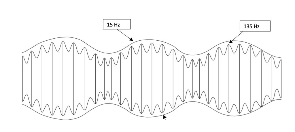
Bearing information to the airborne interrogator is provided by a continuously rotating cardioid lobe rotating in a clockwise direction at 15 revolutions per minute. At the receiving point in the space, this rotating lobe produces a 15Hz sinusoidal signal, where maxima is produced when the lobe is facing the receiving point and minima when the maxima is facing in the opposite direction, with cross overs when lobe maxima is facing 90o and 270o with respect to the receiving point direction. Sinusoidal signal lobe is modulated by a sinusoidal 135Hz signal. This results in nine riding lobes corresponding to each 15Hz cycle. Figure 3 provides information on the rotating lobe.

Resultant pattern is modulated on the assigned RF carrier and is made to rotate at 15 revolutions per minute either by physically rotating the antenna or is simulated in the space by switching an antenna array. This rotating lobe is received in the aircraft and detected as a modulated signal as presented in Fig. 4. It may be noted that for every cycle of 15 Hz, nine cycles of 135Hz are received or 15 Hz is divided into 9 cycles of 135 Hz signal. Each cycle of 135Hz signal thus becomes equal to 40o sector of 15Hz signal. Equiphase points on 135Hz cycles are thus observed at 40o, 80o, 120o, 160o, 200o, 240o, 280o, 320o and 360o on 15Hz signal. In other words, resolution of 40oof 15Hz is magnified to 360o of 135Hz cycle. Precision thus improves by 360/40 = 9 times.
Along with the rotating lobe, identity tone and two burst signals are also modulated on the RF, which are detected along with the 15Hz/135Hz signal in the airborne system.
b. Reference Bursts
Two bursts are also transmitted as phase references for the varying 15Hz/135Hz signals. The phase of variable signals, both 15Hz and 135Hz are compared with the reference bursts to find out the phase difference between the two, which in turn provides the bearing information. Both the reference bursts will be discussed when deriving of bearing information is discussed.
c. Identification Signal
Ground-based beacon also transmits a Morse Code station identification signal at least once every 30 seconds to validate the beacon station selection. While Morse character is keyed, sets of 2 pulse pairs are transmitted at a rate of 1350Hz. The spacing between pulse pairs is 100mS. In aircraft, this identity signal is presented as dots and dashes (Morse Code) of 1350Hz tone. When this identity signal is transmitted, the ground-based transponder does not transmit reply signal, however the ‘memory’ provision in the airborne receiver allows continuation in track mode until valid reply pulses are restored.
Functional Description:
Following paragraphs describe the process adopted in the aircraft to derive bearing information from the received 15Hz and 135Hz tones.
- Coarse bearing information
First, the coarse bearing information is derived in the airborne receiver, using 15Hz signal and the North Bursts. Deriving of information from the two signals is explained in Fig 5.

‘Peak Riding’ detector in the airborne system, detects all the pulse signals including the Bursts. For ‘X’ channels North burst consists of 12 pulse pairs with pulses spaced at 12mS. Separation between pulse pairs is 30mS. For ‘Y’ channels North Burst will contain 13 single pulses (not pairs) with 30mS spacing between them.
Airborne system compares the phase of the 15Hz sinal with the phase of the North Bursts, bearing depends on the phase difference between the two signals. Reading got by measuring the phase difference between North Burst and the 15Hz signa is the coarse bearing information. After determining the coarse bearing information, airborne system then finds out in which of the nine 400. Sectors (135Hz cycle), the bearing lies.
Fine Bearing Information
After the coarse bearing information has been derived, next 135Hz signal is used to refine this information. Similar to the North Burst, Auxiliary Burst signal is used to refine the information by identifying the 400 sector (out of the nine sectors) in which the bearing lies. The process can be explained through Fig 6.

Auxiliary Burst for ‘X’ mode channel contain six pulse pairs spaced at 24mS. The spacing between pulses of a pair is the same as for the reply signal which is 12mS. In ‘Y’ mode, the Auxiliary Burst consists of 13 single pulses spaced at 15mS. Both North and Auxiliary Bursts in ‘X’ and ‘Y’ mode are kept different to support the modes in receiver. Auxiliary Burst is however not transmitted when North Burst is transmitted.
After 135Hz cycle (or 15Hz signal’s 40o sector) has been identified, bearing information within the cycle is derived by measuring the phase difference between the Auxiliary Burst (Reference) and 135Hz signal. This bearing is then incorporated on the coarse bearing to find out the final bearing information.
The Flight Calibration procedure has been in existence since late nineteen fifties, where the following performance conditions have been checked periodically[6]:
- Course sensitivity
- Sensing (to and from)
- Rotation
- Course Alignment
- Polarization
- Orbits 5/25 miles
- Coverage
- Approach Procedures
Also effects of nearby obstructions on TACAN performance are evaluated during flight calibrations to decide if blanking gate are required to be incorporated and the gate size.
Process of calculating bearing can better be explained through an example:
Example:
Pilot of the aircraft selects TACAN channel (and mode) and the airborne interrogator transmits interrogation pulses on assigned interrogation frequency. Interrogation is received in the ground-based transponder and the interrogation pulses are validated for various parameters like pulse width, spacing etc. If the interrogation is found meeting the specifications, reply pulse pairs are generated and transmitted on the assigned reply RF frequency. Beacon identification is modulated in Morse Code and the bursts are also transmitted along with the replies.
Pilot of the aircraft confirms the Identity Code transmitted by the ground-based beacon and this also confirms that the RF channel selected is correct. Reply pulses are validated in the airborne system by checking various parameters. Phase of the received 15Hz signal is compared with the phase of the North Burst. Phase difference between the two indicates coarse bearing of the aircraft with respect to the Magnetic North. Let us assume the coarse bearing information derived is 137o. This coarse bearing lies in the fourth 135 Hz cycle (120o to 160o sector of 15Hz signal).
The phase of the fourth 135Hz signal is compared with the Auxiliary Burst for that cycle. Phase resolution of 135Hz cycle is much better than the phase resolution of 15Hz cycle (theoretically it should be 9 times). Suppose phase difference found between fourth 135Hz cycle and the Auxiliary Burst is 16.5o. The final bearing will then be 120 + 16.5 = 136.5o.
Conclusion:
Radio aids to navigation have evolved since the fifties and have been adopted depending upon their performance and their immunity from environment conditions. TACAN (and many others like Transponder (based) Landing System etc) have been adopted for operation to support operations by standard ICAO navigation aids.